
|
|
|
ElectrochemistryStep 1: -Investigating redox reactions -Practice with redox reactions -Reduction tendencies of metal ions Step 2: Step 3: Step 4: -Practice with non-standard cells Feedback Form: |
Electrochemistry Tutorial: Galvanic Cells and the Nernst Equation >> Step 2: The Electrochemical Cell
Electrochemistry: Galvanic Cells and the Nernst EquationStep 2: The Electrochemical CellIn the movie on the previous page, when a zinc strip is placed in a solution with Cu2+ ions, the following spontaneous redox reaction occurs:
In this redox reaction, electrons are transferred from Zn to Cu2+. Previously, we wrote half-reactions that illustrate the nature of this electron flow:
The electrochemical cell forces the electrons to flow through a wire as they go from Zn to the Cu2+ ions. The electrochemical cell consists of two "half-cells" that correspond to each of the above half-cell reactions. For the half-cell corresponding to the oxidation reaction, a strip of Zn metal is placed in a solution of Zn2+ ions. For the reduction half-cell, a strip of Cu metal is placed in a solution of Cu2+ ions. We then connect these cells together (using a wire and a salt bridge) to create an electrical circuit. The following video explains this setup and details the process at a molecular level:
After watching the video, please complete the diagram below to identify the key components in an electrochemical cell:
Keep in mind that in an electrochemical cell, only the ions travel in solution. The electrons travel between the electrodes on the wire and never enter the solution. The flow of electricity in the circuit is maintained by the electrons moving through the wires and the ions moving through solution.
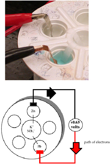
The images to the right show what a carrou cell looks like in the laboratory, and how we depict it schematically. The schematic shows the cell set up for the spontaneous reaction between Zn metal and Pb2+ ions:
We can understand the direction of electron flow by breaking this into half-reactions:
Electrons are leaving the Zn half-cell and going towards the Pb half-cell. A convenient short-hand notation for this is: Zn(s)| Zn2+(aq) || Pb2+(aq) | Pb(s) In this notation, the anode, or oxidation half-cell is on the left and the cathode, or reduction half-cell is on the right. The double vertical line, ||, represents the salt bridge, and the single vertical line represents the phase boundary between a solid metal and its salt solution. A voltmeter is used to measure the potential, or voltage, of an electrochemical cell. Voltmeters have a positive and negative terminal and, by convention, a red wire is connected to positive terminal and a black wire is connected to the negative terminal. The sign of the reading on the voltmeter tells us the spontaneous direction of the electron flow. In the cell: Zn(s)| Zn2+(aq) || Pb2+(aq) | Pb(s), the spontaneous redox reaction corresponds to flow of electrons from Zn to the Pb half-cell. If the black wire is connected to the Zn electrode and the red wire is connected to the Pb electrode, then the voltmeter will show a positive value. If we reverse this, by connecting the black wire to the Pb electrode and the red wire to the Zn electrode, then the voltmeter will show a negative value. Remember: if the voltmeter is showing a positive value, then the spontaneous direction of electron flow is from the black wire to the red wire. A commonly used language in electrochemistry is that of anode and cathode. Electrons flow from the anode (electron provider or electron source) to the cathode (electron receiver or electron sink). If the voltmeter has a positive reading, the black wire is on the anode and the red wire is on the cathode.
|
| Page Last Updated: 06.22.2021 |